13 Jan Optimizing Cooling Efficiency: The Critical Role of Proper Water Line Sizing in Injection Molding
 In the world of injection molding, precision is paramount. From designing the mold to setting process parameters, every detail contributes to the quality of the finished product and the efficiency of the manufacturing process. One often overlooked yet critically important factor is the proper sizing of water lines for cooling. Ensuring water lines are the right size and location for the cavity can significantly impact cycle times, product quality, and operational costs.
Cooling accounts for 60-80% of the injection molding cycle. After the molten plastic is injected into the mold, it must cool and solidify before the part can be ejected. The efficiency of this cooling process directly affects cycle time, dimensional stability, and overall performance of the part. Improper cooling can lead to problems such as warpage and shrinkage, extended cycle times that reduce throughput, increased energy consumption, and poor part quality that necessitates rework or scrap.
Water quality and properly designed cooling systems for the plant are the top priorities for ensuring efficient cooling in the mold. Although the effects are not as dangerous as supplying a machine with undersized electrical wiring, we should consider the importance from a similar perspective. If these supply lines to the machine are not large enough, proper water flow to each circuit in the mold will struggle to maintain turbulent flow and sufficient cooling capacity.
Here are a few rules of thumb that should be considered when designing water lines for injection molds:
- Consider a standard size for cooling channels. Many early adopters chose 7/16″ as this was the drill size of a ¼” pipe tap.
- Using the sized lines mentioned above made the GPM requirement an easy 1.5 GPM or greater for ensuring turbulent flow. Regardless of the size you choose, you must confirm Reynolds numbers are above 4,000 (most target 6,000-8,000 to cover the different viscosities associated with water/glycol solutions and temperature ranges used in molding).
- Distance between each line should be no more than 3 times the diameter (center to center) and 1.5 times the diameter or less from the molding surface.
- Strike a balance between looping circuits vs a direct in/out.
- Bubblers and Baffles should not be looped with other lines as their flow is substantially lower.
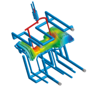
To succeed, manufacturers should collaborate with experts, such as mold designers and process engineers, to determine the optimal water line configuration for their specific applications. Using advanced simulation tools can help model heat transfer and flow dynamics within the mold. Regular maintenance is essential, with periodic inspections and cleaning of water lines to ensure they remain free of blockages and corrosion. Monitoring system performance through flow meters and temperature sensors verifies that the cooling system operates as intended.
If you have any questions about how you can achieve optimal cooling efficiency in your injection molding applications, reach out to Polysource! Our team of experts is ready to assist you with your technical needs, providing solutions that elevate your manufacturing process and enhance product quality.


